
Last Updated: September 16, 2026
A well-designed home network diagram makes it easier to understand how your router, modem, access points, switches, computers, smart TVs, security cameras, and other connected devices communicate. It also helps you troubleshoot connectivity problems, plan upgrades, and keep your network organized.
Whether you are setting up a small apartment network or a larger home with multiple access points, creating a simple diagram gives you a visual map of the entire setup.
What Is a Home Network Diagram?
A home network diagram is a visual representation of the devices, connections, and network segments that make up your home network.
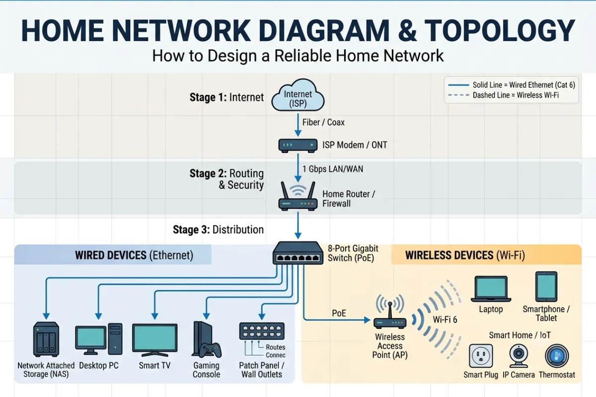
A basic diagram might show an internet connection going to a modem or ONT, which connects to a router. The router then connects wired devices through Ethernet and wireless devices through Wi-Fi.
A more advanced home network diagram can include switches, mesh nodes, wireless access points, VLANs, guest networks, IoT devices, NAS storage, printers, cameras, and smart-home equipment.
Why Create a Home Network Diagram?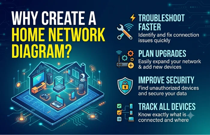
A network diagram is useful even for a relatively simple home setup.
It can help you:
- Identify how devices are connected
- Troubleshoot internet and Wi-Fi problems
- Plan Ethernet cable runs
- Position access points more effectively
- Document your network before making changes
- Identify single points of failure
- Separate trusted and guest devices
- Plan upgrades to switches, routers, or Wi-Fi equipment
- Keep track of important IP addresses and subnets
For larger homes, documentation becomes particularly valuable. If something stops working, you can follow the diagram from the internet connection through the network to the affected device.
Star, Bus, and Mesh Topology Explained
Network topology describes how devices are arranged and connected.
The most common topology concepts you will encounter when designing a home network are star, bus, and mesh.
Star Topology
In a star topology, devices connect to a central networking device such as a switch or router.
Star topology is common in modern wired home networks because each device has a dedicated connection to the central switch.
One advantage is easier troubleshooting. If one Ethernet cable fails, the other connected devices can usually continue operating.
The main dependency is the central device. If the switch fails, devices connected through it may lose network connectivity.
Bus Topology
A bus topology uses a shared communication path.
Traditional Ethernet networks once used bus-style arrangements with coaxial cable and terminators.
This approach is rarely used for modern residential Ethernet networks. Current home networks generally use switched Ethernet instead.
Mesh Topology
A mesh topology uses multiple interconnected nodes.
Mesh arrangements are particularly relevant to whole-home Wi-Fi systems.
Depending on the system, mesh nodes may communicate wirelessly or use Ethernet backhaul.
Wireless mesh can simplify installation because you do not need Ethernet at every node. However, wireless backhaul can reduce available bandwidth depending on the equipment, distance, interference, and network design.
Ethernet backhaul generally provides a more consistent connection between nodes when suitable cabling is available.
How to Draw a Home Network Diagram
You do not need advanced networking knowledge to create a useful diagram.
Start by identifying the main connection entering your home.
This could be a fiber ONT, cable modem, DSL modem, or another ISP-provided device.
Next, identify your primary router. Then map the connections from the router to switches, access points, computers, entertainment devices, and smart-home equipment.
Once the physical connections are mapped, add important logical information such as IP ranges, VLANs, or separate networks.
Step 1: Identify the Internet Connection
Record where your internet service enters the home.
Label the device as ONT, modem, or gateway, depending on your setup.
Step 2: Add the Router
Place the router after the modem or ONT.
If your ISP device also functions as a router, clearly label that device so you know where routing and firewall functions are being performed.
Step 3: Add Switches and Access Points
Add Ethernet switches, wireless access points, or mesh nodes.
Draw wired connections using solid lines and wireless connections using a different line style if your diagramming tool supports it.
Step 4: Add End Devices
Include important devices such as:
- Desktop computers
- Laptops
- Smart TVs
- Game consoles
- Printers
- NAS devices
- Security cameras
- Smart-home hubs
- IoT devices
- Smartphones
- Tablets
You do not necessarily need to document every temporary Wi-Fi client.
Focus on permanent or important devices.
Step 5: Add Network Information
For a more useful technical diagram, add details such as:
| Information | Example |
| Router IP | 192.168.1.1 |
| Main subnet | 192.168.1.0/24 |
| Guest subnet | 192.168.20.0/24 |
| IoT subnet | 192.168.30.0/24 |
| DHCP range | 192.168.1.100–192.168.1.200 |
| Wi-Fi network | Home-WiFi |
| Guest Wi-Fi | Home-Guest |
Avoid putting Wi-Fi passwords or other sensitive credentials directly into a network diagram.
Labeling Devices and Subnets
Good labels make a diagram significantly easier to use.
Instead of writing only Router, use a descriptive label such as:
Main Router – 192.168.1.1
For a switch:
Office Switch – 8-Port Gigabit
For an access point:
Upstairs AP – Ethernet Backhaul
This makes the diagram useful when troubleshooting or upgrading the network.
Use Consistent Naming
A practical naming system could be:
- Router-Main
- Switch-Office
- Switch-LivingRoom
- AP-Upstairs
- NAS-Storage
- Printer-Office
- Camera-FrontDoor
For subnets, document the purpose rather than only the IP address.
For example:
IoT VLAN – 192.168.30.0/24
is more useful than simply:
VLAN 30
Physical vs Logical Network Diagrams
A home network can be documented using two different diagrams.
Physical Network Diagram
A physical diagram shows where equipment and cables are located.
For example:
Internet
|
Router — Living Room
|
Ethernet Cable
|
Switch — Office
|
+— Desktop
+— Printer
+— NAS
This is useful when troubleshooting cables or planning network expansion.
Logical Network Diagram
A logical diagram focuses on network relationships rather than physical locations.
Internet
|
Firewall/Router
|
+— Main LAN
|
+— Guest Network
|
+— IoT Network
|
+— Management Network
Logical diagrams are particularly useful when your home network uses VLANs or multiple subnets.
For an advanced home network, maintaining both diagrams can provide a much clearer picture.
Best Tools for Network Diagrams
You can create a home network diagram with anything from a simple drawing application to dedicated network documentation software.
diagrams.net
diagrams.net, also known as Draw.io, is a popular option for creating network diagrams.
It provides templates and diagramming shapes that make it relatively easy to create a structured network map.
Microsoft Visio
Microsoft Visio provides professional diagramming features and networking templates.
It can be useful for people who already use Microsoft 365 and need more advanced documentation capabilities.
Lucidchart
Lucidchart is a browser-based diagramming platform that supports network diagrams, collaboration, templates, and organizational documentation.
Miro
Miro can be useful when you want to combine network diagrams with planning notes, architecture discussions, or collaborative project work.
Pen and Paper
For a small network, a simple hand-drawn diagram can still be useful.
The important part is documenting the actual connections accurately. A beautiful diagram with outdated information is less useful than a basic diagram that reflects the current network.
Home Network Diagram Examples
Basic Home Network
A basic setup may look like this:
INTERNET
|
MODEM
|
ROUTER
/ \
/ \
Ethernet Wi-Fi
/ \
Desktop Laptop
|
Phone
This arrangement is sufficient for many smaller homes.
Home Network With a Switch
A home with several wired devices may use a switch:
INTERNET
|
ROUTER
|
SWITCH
/ | \
/ | \
PC NAS Smart TV
The switch expands the number of Ethernet connections available to wired devices.
Home Network With Multiple Access Points
A larger home may require additional access points:
INTERNET
|
ROUTER
|
Ethernet Switch
/ \
/ \
AP Downstairs AP Upstairs
/ \ / \
Phone TV Laptop Tablet
Using Ethernet backhaul between access points can help provide a stable connection between wireless access points and the main network.
Home Network With Guest and IoT Networks
A more advanced setup can separate different device categories:
INTERNET
|
ROUTER
/ | \
/ | \
Main LAN Guest IoT
| Wi-Fi |
PCs/NAS Visitors Cameras
Network segmentation can help limit communication between groups of devices when the router or firewall supports appropriate VLAN and firewall configurations.
How to Design a Reliable Home Network Topology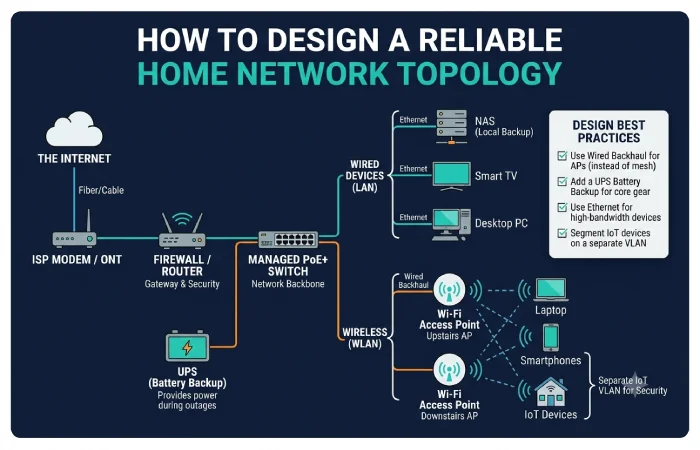
A reliable network starts with a sensible physical layout.
Place the primary router in a location that makes sense for wired connectivity and wireless coverage. Avoid hiding wireless equipment inside cabinets or positioning it next to major sources of interference.
Use Ethernet for devices that benefit from stable, high-throughput connections, such as desktop computers, NAS systems, gaming PCs, and some smart TVs.
Use Wi-Fi for mobile devices and equipment where running Ethernet is impractical.
For larger homes, consider multiple access points rather than relying on a single router to cover every room.
Also identify important single points of failure. If one switch connects every wired device, its failure will affect all of those devices.
Home Network Diagram Checklist
Before considering your diagram complete, check that it includes:
- Internet connection
- Modem or ONT
- Main router
- Switches
- Access points or mesh nodes
- Important wired devices
- Important wireless devices
- Cable connections
- Wireless connections
- IP addresses where useful
- Subnets or VLANs where applicable
- Device names
- Network purpose
- Physical locations where relevant
Update the diagram whenever you replace major networking equipment or significantly change your topology.
FAQs About Home Network Diagrams
What is the most common home network topology?
Star topology is common for modern wired home networks because devices typically connect through a central router or Ethernet switch.
What should a home network diagram include?
A useful diagram should show the internet connection, modem or ONT, router, switches, access points, important devices, and major network connections. Advanced diagrams can also document subnets and VLANs.
What is the difference between a network diagram and topology?
A topology describes how network devices and connections are arranged. A network diagram is the visual representation used to document that arrangement.
Can I create a home network diagram for free?
Yes. Free diagramming applications and even basic drawing tools can be used to create a home network diagram. The key requirement is accurate documentation.
Should I create a physical and logical network diagram?
For a simple home network, one diagram may be enough. Larger or segmented networks can benefit from separate physical and logical diagrams.
How often should I update my home network diagram?
Update it whenever you make a significant change to the network, such as replacing a router, adding an access point, installing a switch, changing subnets, or adding network segmentation.
Final Takeaway
A home network diagram gives you a clear visual map of how your network works. It can simplify troubleshooting, improve documentation, and make future upgrades easier.
Start with the internet connection, modem or ONT, and router. Then add switches, access points, wired devices, wireless devices, and important network information.
For a small network, a simple star topology may be all you need. Larger homes can benefit from multiple access points, Ethernet backhaul, switches, and separate logical networks.
The most useful diagram is not necessarily the most complicated one. It is the one that accurately represents your network and remains easy to understand when you need it.